")
Contact
DMT Petrologic GmbH & Co. KG
Karl-Wiechert-Allee 76
30625 Hannover, Germany
Phone: +49 511 5413917
E-Mail: info dmtpetrologic.com
Common Reflection Surface Processing (CRS)
Common Reflection Surface is a method to describe the kinematics of reflections in seismic reflection data by the means of an analytic traveltime approximation centred at zero-offset. The traveltime formula depends on attributes that are extracted from the seismic reflection data by fitting the operator to the data for all samples. The CRS method describes the traveltime using 8 parameters.
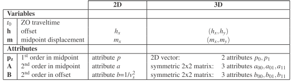
Proprietary Implementation
Our proprietary implementation by Dr. German Hoecht features a high resolution prestack picking of all 8 parameters which ensures azimuth compliant moveout. Besides estimating correctly the dip of the data prestack, we can improve the stacking velocities automatically using CRS and even determine azimuthal dependant velocities.
Partial prestack CRS stacking can be done regularized or into any geometry including the original input geometry. This way we can preserve the acquisition design when applying CRS for noise reduction.
By interpolating into a denser regular grid we can preserve azimuth information and at the same time remove aliasing effects from the data.
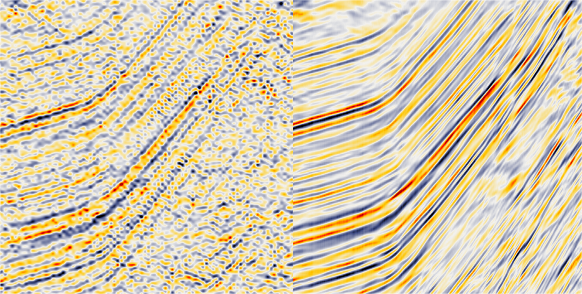
- Figure 1: Left: Before CRS Right: After CRS, aliasing was removed by interpolation towards a denser grid
A major feature of our propriety CRS implementation is the usage of multi-operator and operator-oriented stacking. This results in preservation of conflicting dips and makes attribute smoothing redundant.
- Figure 2: Left: Before CRS Middle: After CRS, geometry preserving Right: After regularizing CRS
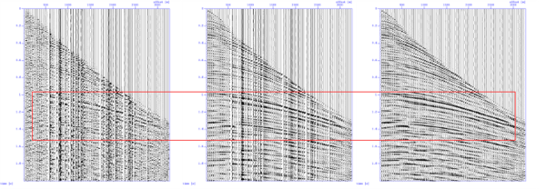
- Figure 3: Left: Before Right: After regularizing CRS
This example shows the interpolation of large gaps in a dataset by applying regularizing CRS. The noise is reduced and the target is much improved by the interpolation and regularization.
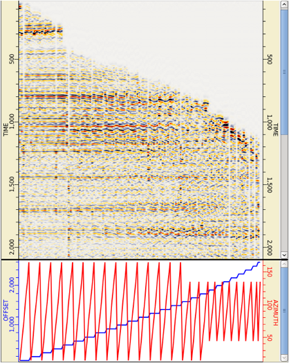
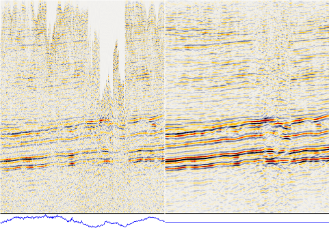
- Figure 4: Gather after 5D regularizing CRS, azimuthal anisotropy is preserved after CRS application
In addition to the interpolation into any given geometry we can regularize into a 5D geometry with offset- and azimuth-bins. The 5 domains are: inline, crossline, azimuth, offset and time., after the interpolation all bins are fully populated and regularized.
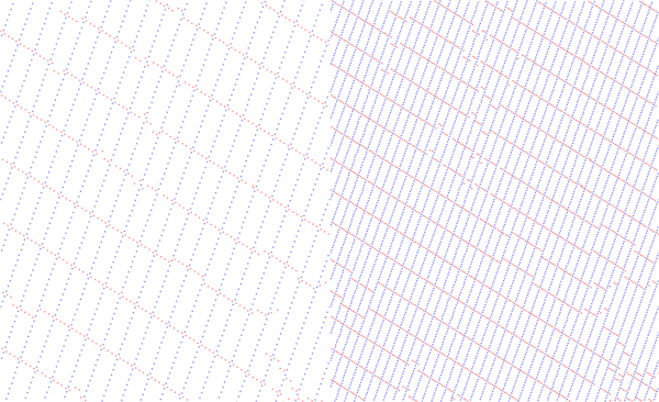
- Figure 4: Left: original input geometry Right: denser output geometry, please note that the scale is identical in both images
Velocity Model Building
Our CRS features 3D NIP-Tomography and 3D Image-Ray-Tomography which convert RMS stacking velocities in time to interval velocities in depth correcting correctly for lateral positioning. Both methods are further explained in the depth imaging section.